
Independent OTDR characterization and certification from 100 m to 220 km. ASAP Computer Services tests and certifies singlemode fiber across San Antonio, South Texas, Central Texas and the Texas Hill Country: Tier 1 insertion loss, bidirectional Tier 2 OTDR at 1310, 1550 and 1625 nm, reflectance and optical return loss, live fiber testing and dark fiber acceptance. Our in-house EXFO MaxTester 730C OTDR fleet covers spans to 77 km. Long-haul OTDR platforms cover single spans to 220 km. Split-span procedures cover everything longer. Independent of the installer, and already onboarded with major prime building fiber in Texas.
Request fiber testing with your fiber count, route length and access points for a quote, or call 210-497-1424.


What we test
Every job is scoped from your fiber schedule and route records, on a known and validated route with documented access points, and tested to TIA-568.3-D, TIA-526-7 and IEC 61280-4-2, or to the carrier, cooperative or grant specification that governs the build. This page covers singlemode plant at 1310, 1550 and 1625 nm.
- Tier 1 insertion loss, length and polarity with an optical loss test set (referenced light source and power meter) at 1310 and 1550 nm
- Tier 2 OTDR characterization of every splice, connector, splitter and bend, shot from both ends with launch and receive fibers
- Reflectance of every connector and optical return loss of every link
- Connector end-face inspection and cleaning to IEC 61300-3-35 before anything is mated
- Live fiber OTDR testing at 1625 nm through a filtered port
- Dark fiber acceptance testing for IRU, lease and purchase transactions
- Fault location: breaks, macrobends, high-loss splices, reflective connectors, crushed or water-damaged sheath
- Post-restoration verification after an emergency splice
- Baseline documentation before a cutover, relocation or system upgrade
- Construction damage assessment: before-and-after trace comparison, the event characterized and bounded to a window on the route for the civil prime to pothole, documentation for a damage claim
- Third-party certification of cable and fibers installed by another contractor, for acceptance and commissioning
What a testing scope includes, and what is a different scope
Testing is measuring a route you already know. It is not finding a route, finding a fiber or fixing one. Each of the scopes below is quoted on its own and carries its own minimum mobilization fee by region, so the quote you get matches the work you asked for and nothing else. A scope that can be bounded from the records is quoted as a fixed price. Work that cannot be bounded up front is hourly, and so is standby: when you ask us to stay on site after the tests are submitted while civil crews inspect, pothole or repair, that is hourly time on top of the scope.
- Testing and certification. Tier 1, Tier 2, reflectance, ORL and end-face inspection on a known, validated route, from documented access points, with the report and files described on this page. This is the scope this page is about.
- On-the-ground fault isolation. A crew walks the route, opens closures, narrows the event to a flagged window on the route, documents what is visible and recommends the fix. Separate troubleshooting scope, quoted when you ask for it. Exposing the cable to confirm the cause is potholing, and potholing is the civil prime’s work.
- Route validation and fiber identification. Finding where a cable actually runs, identifying unlabeled fibers, tracing a route with no records or correcting records that turn out to be wrong. A different statement of work entirely, not a line item on a testing quote. If a testing job runs into it, testing stops at that point and the validation work is written as a change order before it continues.
- Remediation. Re-dressing a closure, a re-splice or a section replacement, by your prime’s crew or by our fiber splicing teams as its own scope, followed by a verification scope on every affected fiber.
- Standby. Staying on site after the tests are submitted, while civil crews inspect, pothole or repair, and re-shooting fibers as they go so the crew knows when the repair is good. Hourly, on top of whichever scope brought us out, with the mobilization minimum.
Not sure which scope fits? Contact us with what you know about the route and the records you have, and we will tell you which one you are buying before anything is quoted.
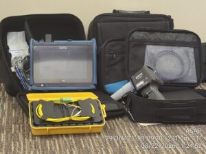
When to call for independent fiber testing
Three situations bring most of the calls to this page. Each one ends the same way: traces and a report produced by someone other than the installer or the contractor whose work is in question.
Construction is suspected of damaging your cable plant
A bore crew, a trencher or a road project crossed your route, the locate ticket was closed, and now a fiber is dark or a link is throwing errors. Or nothing is failing yet and you want to know whether the cable was touched. Both are OTDR questions. We shoot the affected fibers from the documented access points, and from both ends where access allows, and read the trace against your baseline. A new event inside the window where the crew was working is what the trace can tell you.
A test characterizes the fiber. It does not prove damage. The report converts the optical distance to a bounded window on the route using the cable’s helix factor and your route and slack records, classifies the event as a break, a crushed sheath or a bend, and includes the dated traces and the before-and-after comparison where a baseline exists. Proving that what is in the window is construction damage means exposing the cable, and that is potholing by the civil prime, not a test. The report is what the prime potholes from, and it is the paper a damage claim, an insurance claim or a dispute with the excavator is built on. A clean baseline and a trace that is no longer clean is the strongest version of that paper; the proof still comes out of the ground. Walking the route to narrow the window and flag it is the on-the-ground troubleshooting scope, quoted separately with its own mobilization minimum.
If a project is about to cross your route, test before it starts. A baseline trace per fiber is scoped like any other test, mobilization minimum included, and it turns a later suspicion into a measurement. Contractors working near existing fiber ask for the same baseline for the opposite reason: proof that the plant was intact when they left. Both assume a documented route; a route that has to be found first is a route validation scope, not a test.
You need third-party certification for commissioning
The cable is installed, the installer has test results, and the owner, the engineer of record, the carrier or the funding agency wants results from someone who did not install it. That is third-party certification, and it is a large share of our acceptance testing. We test to the governing specification, TIA-568.3-D Tier 1 and Tier 2 unless the contract says otherwise, using referenced methods, and we report every fiber against its loss budget as pass, fail or marginal with the location of any failure.
Native .sor files ship with the reports so your engineer can open the traces rather than trust a summary. A failing fiber is reported as failing, with enough detail for the installer to fix it before acceptance. The result is a certification package that holds up for acceptance, retainage release, a grant closeout milestone or a system turn-up, because it was produced independently.
You need the fault found, then handed to your prime for the repair
Owners and primes with their own construction and splicing crews often need one thing from us: find it. Finding it is not construction, and keeping the two separate means the fiber installation team rolls with the right materials. It comes in two scopes. The testing scope locates the fault optically: OTDR and power meter from the documented access points, on the live-fiber protocol when the sheath carries traffic, reported as affected fibers, distance to the event from each end in sheath meters, the corresponding route position from your records, and the event type. The troubleshooting scope, priced separately with its own mobilization minimum, puts a crew on the ground to chase it down: walk the route, open closures, narrow the event to a flagged window, document what is visible and recommend the fix, whether that is re-dressing a closure, a re-splice or a section replacement. Where the cable has to be exposed to confirm the cause, that is potholing by the civil prime.
Either report is written so your prime’s crew can work from it. Your prime makes the repair. We return under a verification scope, test every affected fiber bidirectionally, and the post-repair traces become the new baseline. If you would rather we stay on site while the civil crew potholes and repairs, re-shooting as they go, that is hourly standby on top of the scope. If your prime is not mobilized for the repair, ASAP’s splicing teams can make it as a remediation scope, and it gets tested the same way. All of this assumes the route is known and validated; if the cable or the fiber has to be found first, that is a different statement of work.
If one of these is your situation, contact us with the route records and access points you have and we will scope it.
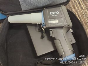
Testing range: 100 m to 220 km, and split spans beyond
Span length, splice count and wavelength decide the instrument and the method. The three tiers below cover everything from a 100 m riser to a multi-hut long-haul route.
| Span | Typical work | Instrument | Method |
|---|---|---|---|
| 100 m to 77 km | Building backbones and risers, campus loops, data center interconnects, FTTx feeder and distribution, cell site backhaul, metro rings, and metro-to-Hill Country segments such as San Antonio to Boerne, New Braunfels, Seguin, Pleasanton or Hondo. | EXFO MaxTester 730C OTDR fleet, owned and on the truck. | Tier 1 plus bidirectional Tier 2 at 1310 and 1550 nm, 1625 nm on live fiber. Short pulse widths for event resolution, launch and receive fibers from 150 m up to 1 km. |
| 77 km to 220 km, single span at 1550 nm | Regional and long-haul transport, intercity dark fiber, wholesale and IRU acceptance. Examples by highway distance: San Antonio to Austin about 130 km, San Antonio to Kerrville about 105 km, Austin to Waco about 165 km, San Antonio to Victoria about 190 km. | Long-haul OTDR platform rented per project, selected for the dynamic range the span and splice count require. | Bidirectional Tier 2 at 1550 nm with long pulse widths and multi-kilometer launch and receive fibers. 1310 nm added where the budget allows or by segment. |
| Beyond 220 km, split span | Routes that exceed a single span or carry enough splices to consume the budget. Examples by highway distance: San Antonio to Corpus Christi about 230 km, San Antonio to Laredo about 250 km, San Antonio to Houston about 320 km, San Antonio to the Rio Grande Valley about 380 km. | Long-haul OTDR from both ends and from intermediate access points: regen and amplifier huts, POPs, splice closures. | Each segment tested bidirectionally from its access points so every splice is characterized from both sides. Closing splices verified from each end. Traces delivered per segment with a route summary that carries every event end to end. |
Highway distances are shown for orientation only. Installed sheath length runs longer than road mileage because of slack loops, closures and routing, so every span is classified from the cable records, not the map. Single-span figures apply at 1550 nm; at 1310 nm attenuation is higher and long routes are tested by segment.
Wavelength strategy: 1550 nm first, 1310 nm for comparison, 1625 nm on live fiber
Our default OTDR wavelength is 1550 nm. Attenuation is lowest there, which gives the longest reach and the cleanest trace on a long span, and it is the band most transport and DWDM systems actually run in, so the results describe the link the way the equipment will see it. It is also more sensitive to macrobends than 1310 nm, so a marginal bend in a closure or a tight slack loop shows up before it becomes an outage.
We add 1310 nm on links that will carry O-band traffic, on premises and campus plant where the electronics run at 1310 nm, and whenever a dual-wavelength comparison is needed to separate bend loss from splice loss. An event that loses more at 1550 nm than at 1310 nm is a bend, not a splice, and that distinction tells the splicing crew whether to re-splice or re-dress the closure.
When the fiber is live we test at 1625 nm through a filtered port. The test pulse stays outside the traffic bands and the traffic stays out of the OTDR receiver. We never launch 1310 nm or 1550 nm into an in-service fiber, and we confirm the fiber state with a power meter before any connection, because amplified long-haul systems carry power that can damage an unfiltered instrument.
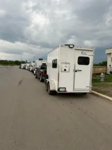
How a test is run
- Records review and loss budget. We take your fiber schedule, route drawings, splice locations, cable type and connector types, confirm the route and access points are documented and validated, and calculate the budget per wavelength before anyone leaves the shop. A route that cannot be validated from the records is quoted as a route validation scope before testing is scheduled.
- Safety and fiber-state check. A power meter goes on every fiber before an instrument does, to confirm it is dark and to identify live or amplified fibers that move to the 1625 nm procedure.
- Inspect and clean. Every end face is inspected to IEC 61300-3-35 and cleaned until it passes. This step clears most connector faults before a single trace is shot.
- Tier 1. Insertion loss, length and polarity per fiber with a referenced light source and power meter.
- Tier 2. Bidirectional OTDR at the scoped wavelengths, with the cable manufacturer’s index of refraction and helix factor set, pulse width matched to the span, and launch and receive fibers long enough to clear the dead zone on both ends.
- Analysis. Events are averaged bidirectionally, compared against the budget and the governing specification, and flagged per fiber as pass, fail or marginal.
- Delivery. Traces, reports and a fiber schedule in your naming, with every failure located along the route so your crew, your prime’s crew or ours can go straight to it.
Where we test fiber
Crews mobilize from San Antonio. Every scope carries a minimum mobilization fee priced by region, so a small verification job near the metro and a large acceptance test in the Valley are each priced for what they are. All regions are listed on our service areas page; for a route that runs outside them, contact us with the end points.
San Antonio
Bexar County and the metro: San Antonio, New Braunfels, Seguin, Schertz, Cibolo, Boerne, Helotes, Castroville, Floresville and Pleasanton. Data centers, hospitals, campuses and the metro rings that tie them together.
South Texas
Laredo, Corpus Christi, Victoria, Eagle Pass, Del Rio, Uvalde, Alice, Kingsville and the Rio Grande Valley from McAllen to Harlingen and Brownsville. Long-haul and middle-mile routes along I-35, I-37, US-77, US-281 and US-83, border crossings, ports and the grant-funded builds bringing fiber to rural South Texas. See the South Texas service area page.
Central Texas
Austin, Round Rock, Georgetown, San Marcos, Kyle, Buda, Killeen, Temple, Waco and the I-35 corridor between San Antonio and Waco. Data center campuses, semiconductor and manufacturing sites, university networks and the regional transport that feeds them. See the Central Texas service area page.
Texas Hill Country
Kerrville, Fredericksburg, Comfort, Bandera, Wimberley, Dripping Springs, Blanco, Johnson City, Marble Falls, Burnet, Llano and Junction. Cooperative fiber-to-the-home builds, ranch and resort campuses, and rural routes where long slack loops and limited access points make accurate span classification matter. See the Texas Hill Country service area page.
Who hires us for fiber testing
- Carriers, ISPs and wholesale fiber providers that need independent acceptance testing on new builds and IRU handovers
- Electric cooperatives and municipal broadband projects with specification-driven, grant-funded builds that require documented Tier 1 and Tier 2 results
- General contractors and low-voltage contractors that install fiber but do not own long-range OTDR equipment, or want third-party certification
- Engineering firms that need a testing contractor independent of the installer
- Data centers, hospitals, school districts, universities and campuses verifying backbone, interconnect and dark fiber before cutover
- Property owners and tenants who need a fault located and a restoration verified
- Infrastructure and broadband construction primes that need an onboarded testing subcontractor for acceptance, troubleshooting or third-party certification on Texas builds
- Contractors working near existing fiber who want pre-construction baseline traces on file before they dig
Already onboarded with the primes building fiber in Texas
We are an onboarded subcontractor with major infrastructure and broadband construction contractors building fiber in Texas. The vendor packet is on file: subcontract agreement, certificate of insurance at the limits their contracts require, W-9, safety program and OSHA documentation. When testing is needed on one of their projects, a work order or purchase order can be issued without a new vendor setup, and billing follows their pay application process with the Texas statutory conditional and unconditional waiver forms.
For primes we have not worked with yet, the same packet is ready to send; request it through our contact page. We are also an SCTRCA-certified SBE and ESBE (#225121307), which primes can count toward small business participation on public work in the San Antonio region. Every scope we take on a prime’s project, testing, troubleshooting, verification or remediation, is written with its own mobilization minimum, fixed where the scope can be bounded from the records and hourly where it cannot, with standby billed hourly when your crews want us on site after the tests are in, so the purchase order and the invoice match.
What you receive
- EXFO iOLM reports with the link map and per-element diagnosis for every fiber
- Native OTDR trace files in .sor format for every fiber, wavelength and direction, readable in any OTDR analysis software
- Bidirectionally analyzed reports with an event table per fiber: location, loss, reflectance and event type
- Tier 1 insertion loss, length and polarity results per fiber
- End-face inspection images with pass or fail grading
- Loss budget comparison and a pass, fail or marginal status per fiber
- A fiber schedule that follows your naming convention and strand numbering
- For split spans, per-segment traces and a route summary that carries every event end to end
Fiber optic testing FAQ
What is the difference between Tier 1 and Tier 2 fiber optic testing?
Tier 1 testing uses an optical loss test set, a calibrated light source and power meter, to measure the end-to-end insertion loss, length and polarity of each fiber against its loss budget. Tier 2 testing adds an OTDR trace that characterizes every splice, connector and bend along the link and measures reflectance and optical return loss. TIA-568.3-D requires Tier 1 and treats Tier 2 as optional, but most carrier, cooperative and grant-funded specifications require both. We perform both on every fiber unless your scope says otherwise.
Why is 1550 nm your default OTDR wavelength?
Three reasons. Fiber attenuation is lowest at 1550 nm, which gives the longest reach and the cleanest trace on a long span. Most transport and DWDM systems operate in the C-band around 1550 nm, so the results describe the link the way the equipment will see it. And 1550 nm is more sensitive to macrobends than 1310 nm, so a marginal bend that would pass at 1310 nm shows up. We add 1310 nm when the link will carry O-band traffic or when a dual-wavelength comparison is needed to separate bend loss from splice loss, and we switch to 1625 nm when the fiber is live.
Can you test fibers that are carrying live traffic?
Yes. Live fibers are tested at 1625 nm through a filtered OTDR port, which keeps the test pulse outside the traffic bands and keeps the traffic out of the OTDR receiver. Before any connection we confirm the state of the fiber with a power meter, because amplified long-haul systems can carry power levels that damage an unfiltered instrument. We never launch 1310 nm or 1550 nm into a fiber that is in service.
How far can you test in a single OTDR shot?
Our in-house EXFO MaxTester 730C fleet characterizes spans up to 77 km at 1550 nm, which covers building, campus, metro, FTTx and most Hill Country routes. For single spans between 77 km and 220 km we bring in long-haul OTDR platforms with the dynamic range and pulse widths that distance requires. Beyond 220 km, or when the splice count consumes the loss budget before the far end, we split the span at an intermediate access point and test each segment bidirectionally.
Why do you test in both directions?
A single-direction OTDR trace can show a splice as a gain, or understate its loss, when the two fibers have different backscatter coefficients or mode field diameters. Shooting from both ends and averaging the two readings for each event produces the true splice loss. Launch and receive fibers on both ends also place the near-end and far-end connectors where they can be measured. Bidirectional averaging is the method TIA and IEC recognize for splice loss, and most carrier and cooperative specifications require it.
What do we receive when testing is complete?
EXFO iOLM reports, native OTDR trace files in .sor format for every fiber, wavelength and direction, bidirectionally analyzed reports with an event table for each fiber showing location, loss and reflectance, Tier 1 insertion loss and length results, connector end-face images with pass or fail grading, a loss budget comparison with a status for every fiber, and a fiber schedule that follows your naming. Files are delivered electronically and can be imported into your own analysis software. The testing scope ends at that report. If you want the problem chased down on the ground, walking the route, opening closures and narrowing the event to a flagged window on the route, that is a separately priced troubleshooting scope with its own mobilization minimum, and we will quote it. The cause is confirmed when the cable is exposed, which is the prime’s civil work where that means potholing.
How do you build the loss budget?
We calculate the budget from the cable records before testing: fiber length multiplied by the attenuation coefficient for each wavelength, plus the number of splices and connector pairs multiplied by their allowed loss. TIA-568.3-D allows up to 0.3 dB per splice and 0.75 dB per connector pair, but we also hold results against the manufacturer’s typical values and your system’s power budget, because a link that passes TIA maximums can still fail a DWDM or PON design margin. Every fiber in the report shows measured loss against the budget.
Do you test dark fiber before a lease or purchase?
Yes. Dark fiber acceptance testing documents the condition of a route before you take it on, and again at handover so there is a baseline for any later dispute. We test bidirectionally at 1310 nm and 1550 nm, record every event, measure optical return loss, and report the results against the attenuation and splice loss limits written into the IRU or lease. If the route is longer than a single span, we test it in segments from the access points listed in the route documentation.
Can you tell whether construction damaged our fiber?
A test characterizes the fiber. It does not prove damage. We shoot the affected fibers from the documented access points, and from both ends where access allows, and compare the new trace to your baseline if one exists. If a new event is there, the trace gives its type and its optical distance: a clean break shows as a reflective end of fiber short of the far end, a crushed or pinched sheath as a new non-reflective loss event, a cable pulled into a bend by a shifted duct or a disturbed closure as loss that grows from 1310 nm to 1550 nm to 1625 nm. Converted through your route and slack records, that distance becomes a bounded window on the route, not a point. Proving that what is in that window is construction damage means exposing the cable, and that is potholing by the civil prime, not a test. What the report gives the prime is a defensible window to pothole, the event type, the dated traces and, where a baseline exists, the before-and-after comparison. A damage claim, an insurance claim or a dispute with the excavator is built on that paper, and the proof comes out of the ground. If there is no baseline, we establish one on the same mobilization so the next project near your route is measured against a record. This assumes a documented route; if the route itself has to be found, that is a route validation scope, not a test.
Can you certify fiber that another contractor installed?
Yes, and that is a large share of our acceptance testing. Owners, engineers of record, carriers and funding agencies often require Tier 1 and Tier 2 results from a tester that did not install the cable, so the certification is independent of the installer. We test to the governing specification with referenced methods, report every fiber as pass, fail or marginal with the location of any failure, and deliver the native .sor files alongside the reports so your engineer can review the traces directly. A failing fiber is reported as failing. That independence is what makes the results usable for acceptance, retainage release, a grant milestone or a disputed result between an installer and an owner.
Do you locate the fault and hand the repair to our prime contractor?
Yes, in two scopes. The testing scope locates the fault optically: we shoot the affected fibers from the documented access points and report the affected fibers, the distance to the event from each end, the corresponding route position from your records, and the event type. The troubleshooting scope, priced separately with its own mobilization minimum, puts a crew on the ground to chase it down: walk the route, open closures, narrow the event to a flagged window, document what is visible and recommend the fix. Where the cable has to be exposed to confirm the cause, that is potholing by the civil prime. Either report is written so your prime’s crew can work from it. Your prime makes the repair, and we return under a verification scope to test every affected fiber bidirectionally and update the baseline, or stay on site as hourly standby while the civil crew works, re-shooting as they go. We are already onboarded as a subcontractor with major infrastructure contractors building fiber in Texas, so the work order usually moves without a new vendor setup. If your prime is not mobilized, our own splicing crew can make the repair as a remediation scope and we test it the same way afterward.
Do you find lost or undocumented fiber routes?
Not under a testing scope. Testing assumes a known, validated route with documented access points and a fiber schedule: we connect at those points and characterize what is between them. Finding where a cable actually runs, identifying unlabeled fibers, tracing a route that has no records, or validating records that turn out to be wrong is a different scope of work entirely, quoted as its own statement of work with its own mobilization minimum. If a testing job reaches a point where the route or the fiber cannot be identified from the records, testing stops there and the route validation work is written as a change order before anyone keeps going. Knowing this up front is what keeps a testing quote priced as testing.
Schedule fiber testing and confirm availability
Send the fiber schedule, route drawings or a plain description of the span and its access points, with the dates you need, and we will confirm crew and instrument availability and schedule the work. Every scope carries a minimum mobilization fee by region. Request fiber testing or call 210-497-1424. Credentials and verification links are on our licensing and certifications page.
